There are six sets of smart vortex street flowmeters at a refinery's finished oil bulk station. They only monitor the loading of vehicles, and the measurement is based on the balance of the ground. Asked the reason, said smart vortex flowmeter is not allowed. Because the two support brackets of the flow sensor are all supported on the measuring tube of the sensor, this is absolutely not allowed. Intelligent vortex flowmeter sensor installation, in particular, put forward the following installation principles: In order to eliminate the unbalanced stress generated when the measuring tube is installed • No support point is required on the measuring tube; a short tube and two short tubes are required at both ends of the measuring tube. The support point should be moved to the left and right to the dotted line in the figure. In order to achieve the support of the pipe by the support frame, and then by the pipe flow measurement tube, never allow the mountain to measure the pipe support the two sides of the pipe. Encapsulated O-Ring ,Teflon Encapsulated O Ring,Fep Encapsulated Silicone O Ring,Ptfe Encapsulated Viton O Ring Ningbo Robon Sealing CO.,LTD , https://www.robonseal.com
Analysis: On-site inspection found:
(1) The six sets of smart vortex flowmeters are three sets (three loading stations) loaded with diesel fuel, and three sets (three loading platforms) are equipped with gasoline, all relying on the difference in the storage tank position (higher than the flow rate More than ten meters of location) Self-loading vehicles, no pressurized oil pump, so only one parking space when loading. This situation appears. It appears that the user does not understand. This intelligent vortex flowmeter has a large pressure loss and can exceed 0.1 MPa.
(2) Six intelligent vortex street flowmeters are regularly sent for inspection every year, and all plum tests are qualified ((level 0.2). When they are taken back after reset, they have a large difference from the ground balance, up to a few percent. Dare to do metering.
(3) The installation of six smart vortex street flow sensors failed. This is the main reason for the abnormal operation. The actual installation is as shown in the figure: 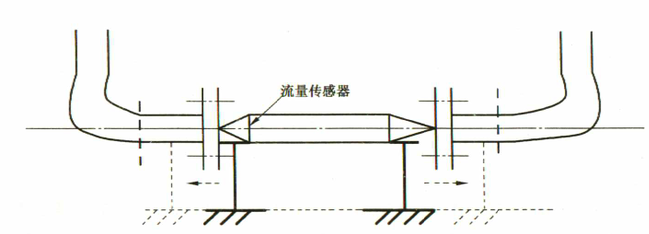
(4) According to the operator of this post, when the six smart vortex flowmeters were dismantled for inspection, the flanges (mouth) of the pipelines on the two sides of the six smart vortex flowmeters were neither parallel nor concentric. The dislocation of flanges on both sides is very serious. The pipelines on both sides have large misalignment, and they are forced to pull hard and hard, and put them on the measuring tube of the intelligent vortex flowmeter. Can the measurement tube not produce unbalanced stress? With stress, the measurement certainly cannot work normally. To solve this problem, it is recommended that they actively create rectification conditions. After adding a short length of flanged pipe (approx. 200 mm long) at both ends of the flow measuring tube, the assembly is tight (without stress), and the whole is not stress-welded in the two. On the end of the pipe (of course not engage in stress-free welding, hose connection can also be changed).